LH-FRS
Material Specification
MS1073 : Part 3 : 1996 BS 476 : Part 22 : 1987LH-FRS MS1073 : Part 3: 1996 BS 476 : Part 22 : 1987
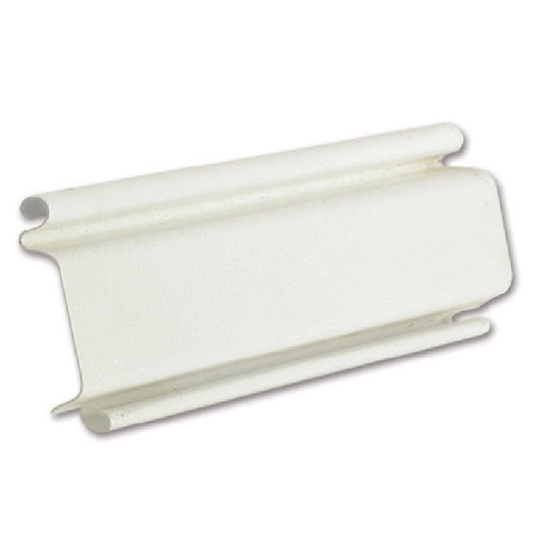
Shutter Curtain
Roll formed from first grade high quality phospahated galvanised steel with interlocking groove and advance design auto cut-off edge end lock to achieve maximum holding strength to each interlocking lath. Curtain design to be LH-C (single skin design), or LH-VIS (double skin). Material specification accordance to JIS G3302 SGCCPHOSPHATED.
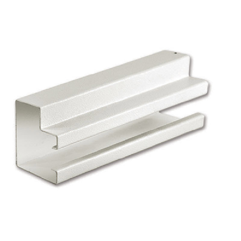
Side Guides
Fabricated from first grade steel sheets with groove about 75mm depth. Concealed to wall type design LH-M015 (1.5mm thick) and exposed face fixed type design LH-F20 (2.0mm thick) or LH-F025 (3.0mm thick). Material specification accordance to JIS G3302 SGCC-ZSCVZ 18.
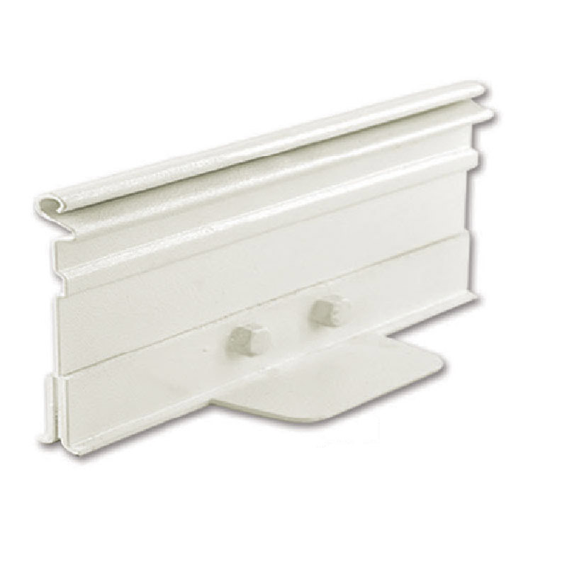
Bottom Bar
For single skin curtain, model : LH-T012 constructed from two pieces hot dipped galvanised steel angles of 38mm x 38mm x 3mm thick bolted together as T-shape section, or LH-F28 flat bar design. Model : LH-VIS, constructed from double wall steel 0.8mm thickness ended by U-shape capped, with 73mm height for stability, special design for double skin curtain. Material specification accordance to JIS G3302 SGCC.
Shutter Box
Fabricated from 1st grade steel hollow sections with galvanized steel sheets covers with corner folded edge to achieve maximum strength, minimum thickness of 1.2mm of minimum size 25mm x 50mm or 38mm x 65mm welded to the heavy duty endplate of minimum of 5.8mm thickness.
Drive Barrel
Fabricated from British Standard Welded Steel Pipes BS 1387 or JIS G3452 with both sides solid steel shafts supported by enclosed bearings to both heavy duty end plates. All drive shafts shall be of solid steel shaft in single piece and fabricated from two heavy duty flange as standard and fully welded to the edge of barrel steel pipe both end. Barrel pipe size to be selected according to fire test and assessments from fire test laboratory for correct diameter to be assembled to each individual size of fire shutters width & height.


Shaft Support
All the support bearings and bearing housing shall be designed & bolted to the heavy duty endplates at both side. Each bearing housing must provide with 4 pieces of bolts and nuts tightened to the end plates as standard. All hanging bolts shall be set as fire rated tested specifications according to the BS or MS specifications.
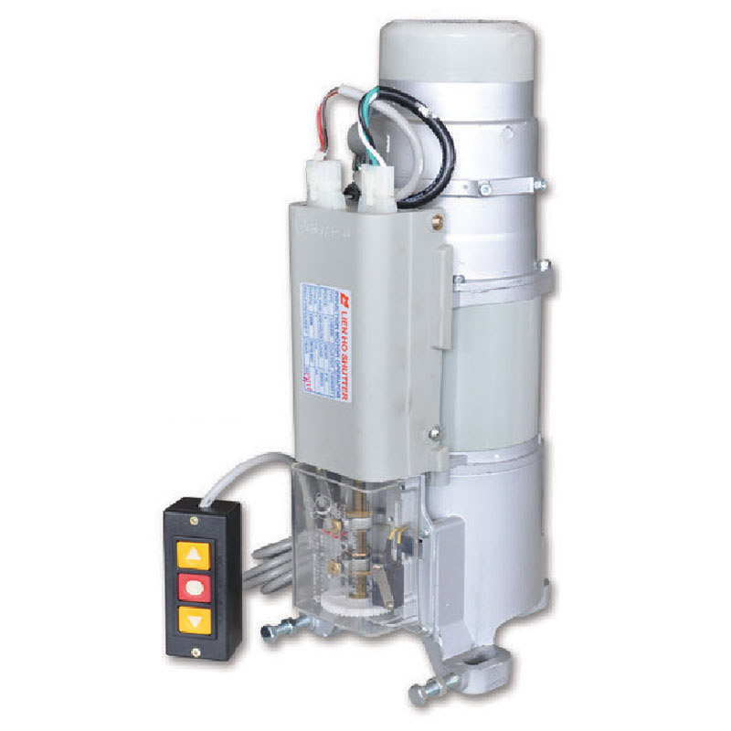
Operation Control
The control for opening and closing of shutters by means of 3 ways push button switch. Each motor is equipped with built in thermal protector, reduction speed gear box, manual override chain when power failure occurs, limit switches for setting upper and lower limit of shutter travel, minimum design of insulation class E, built in release level for gravity close as standard. Power source available in 230v single phase S0Hz and 41 Sv three phase S0Hz. A power switch over relay of 24vdc for auto close when fire signal received as standard. Selection of power source according to manufacturer standard for various size of shutter door opening width and height.
Fire Mode Control Sequence
Standard fire mode operation is direct fully close design. Fire Shutter closed down fully when fire signal is received.
Optional Fire Mode Accessories
Emergency Releser – When shutter received 24V DC (400mA) fire signal from Building Management System, shutter will fully closed down by gravity force.
Thermal Fuse – When room tempreture reached 90C degree, fire shutter will fully closed down by gravity force. Timer Delay – It allow the shutter to closed in 2 stage blocking the smoke spread thru and allow people escape in preset time.
Shutter Finishing
Steel Natural finishing, Powder coating.
Optional Accessories Items
Remote Control, Safety Edge Sensor.
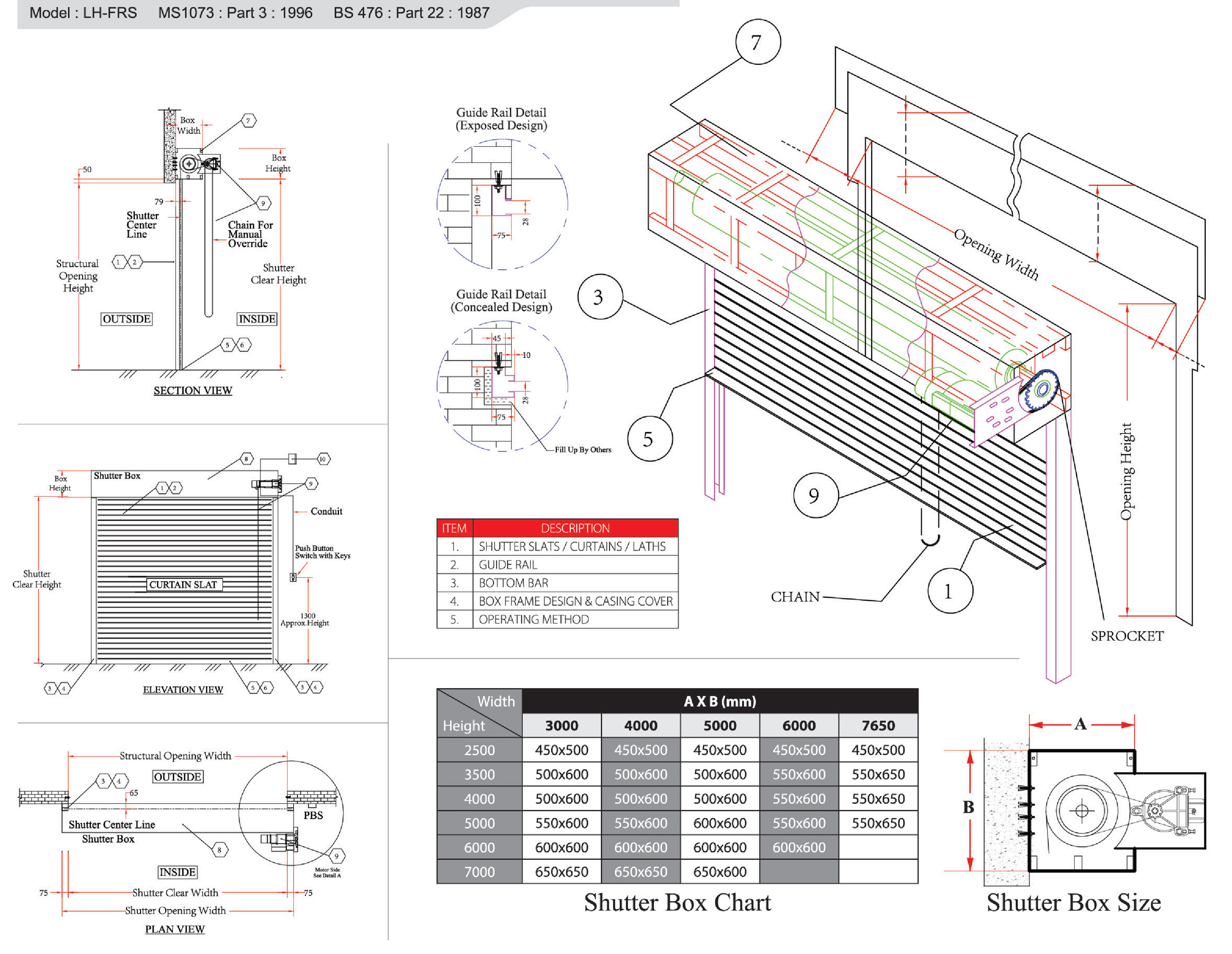
Technical Drawing
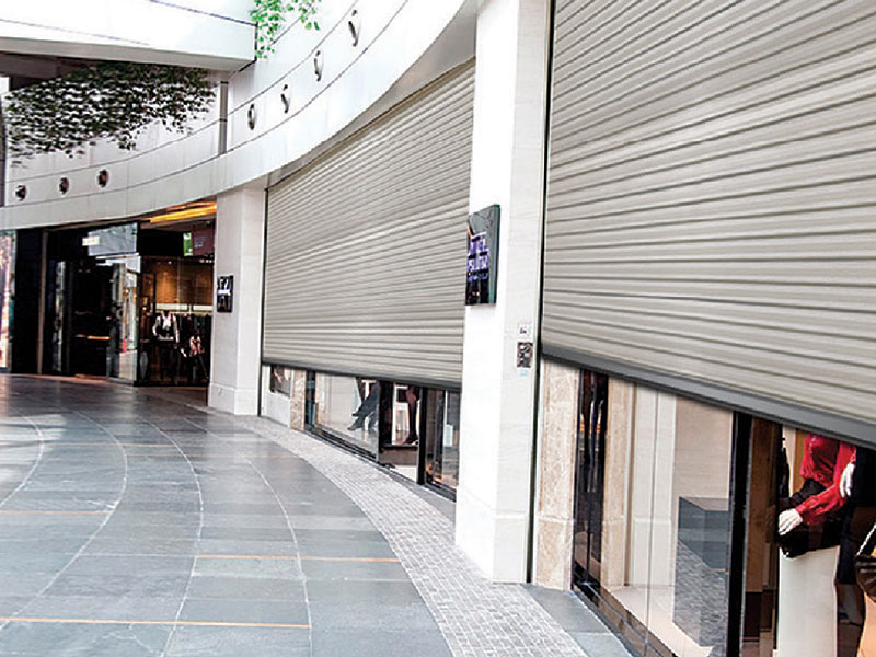
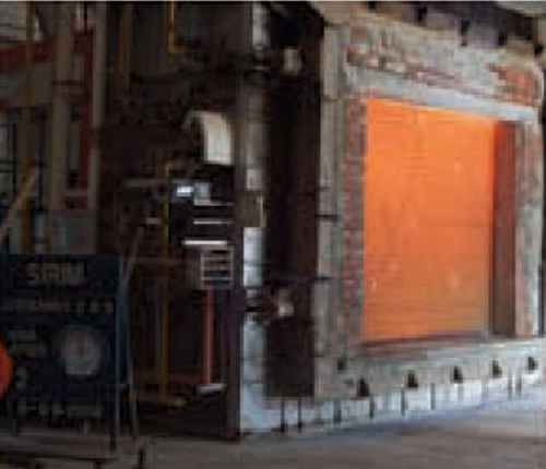
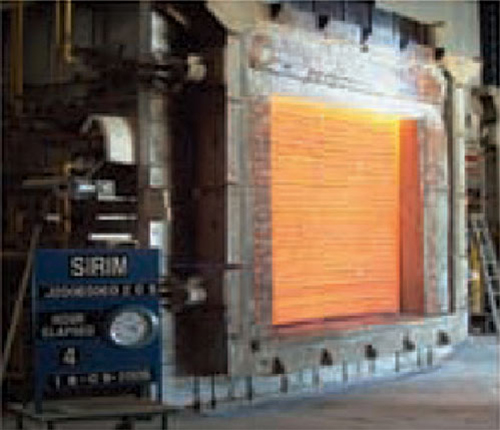
- High integrity fire shutter arduous locations including commercial & industrial applications.
- Available in galvanised mild steel, pre-painted [60microns] & stainless steel construction.
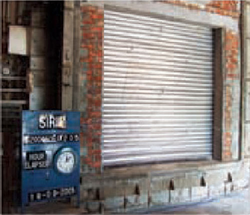
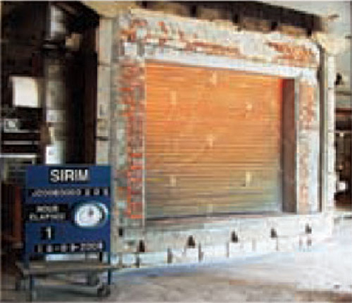
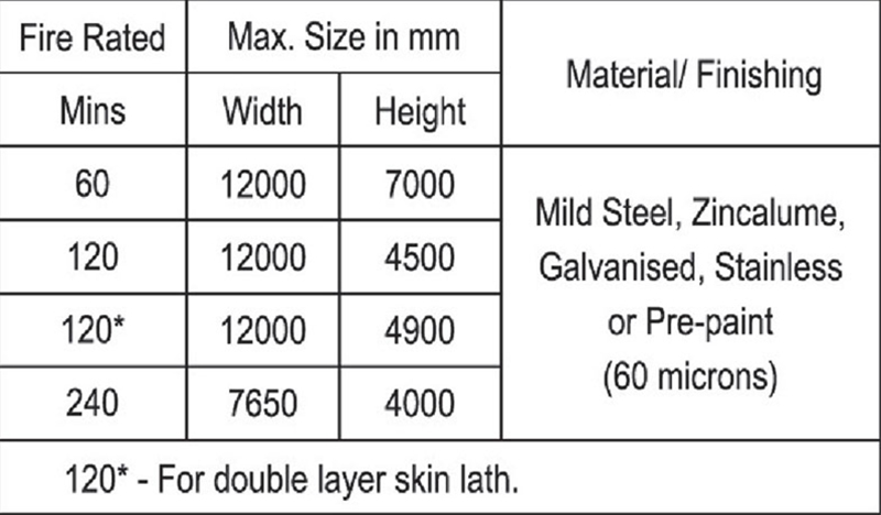
- Up to 4 hour fire integrity rated in accordance with MS 1073: Part3: 1996 and B5476: Part22:1987 for vertical installations.
- Suitable for motorised & thermal fusible link [90° c] operations.
©We reserve the right to change or modify specification without alteration to this leaflet. Pictures shown tor illustration purposes only. This brochure does not fonn part of any contract.
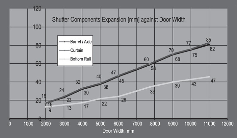
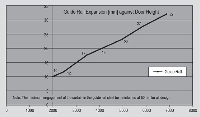
Note : The calculations referred to below tables concern the expected stability of the critical components At elevataed temperatures up to 240 minutes FRP [Fire Resistance Periods] which is based on Warrington Fire Research Centre, WFRAAssessment Report. (Report available upon request only.)